Apr 30, 2019 By Team YoungWonks *
In this blog, we shall look at what is a multimeter and what are its functions?
What is a multimeter?
A multimeter or a multitester, also also called a VOM (volt-ohm-milliammeter), is an electronic measuring instrument that performs several measurement functions in one unit. A typical multimeter can be used to measure voltage, current and resistance and even to check for conductivity.
Analog multimeters uses a microammeter with a moving pointer to show the readings. Digital multimeters (DMM, DVOM), meanwhile, have a numeric display, and can also display a graphical bar indicating the measured value. Digital multimeters are now more common due to their lower cost and higher precision, although analog multimeters continue to be preferred in some instances, especially when one has to track a rapidly changing value.
A multimeter can be a hand-held device useful for basic fault finding and field service work, or a bench instrument which can calculate to a high degree of accuracy. Multimeters come with an array of features and at different price points. Some cost less than $10, while laboratory-grade models with certified calibration can cost upwards of US$5,000.
How to use a multimeter?
As mentioned earlier, a multimeter is used to measure voltage, current and resistance and even to check for conductivity. So let’s look at how the multimeter is used to measure each of these.
Using a multimeter to measure the voltage
Before we look at how a multimeter is used to measure the voltage, let’s look at the term voltage itself. Now voltage is basically the difference in electric potential between two points. This difference in electric potential between two points (i.e., voltage) in a static electric field is defined as the work needed per unit of charge to move a test charge between the two points. In the International System of Units, the derived unit for voltage is named volt and voltage is symbolically denoted by V.
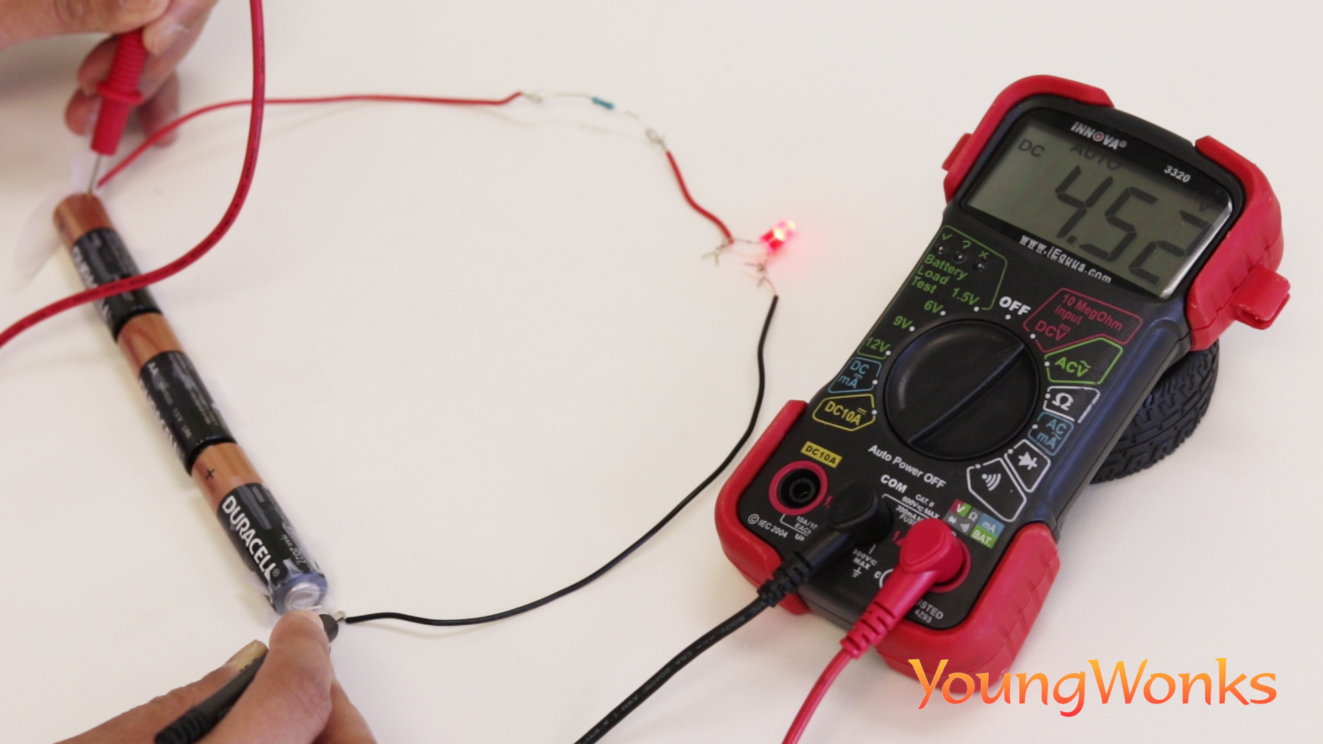
Now if we wish to measure the voltage across the terminals of the AA batteries, here’s how you can do it. As shown in the image below, connect the black probe into COM and the red probe into mAVΩ. Set the multimeter to 2V in the DC (direct current) range. This is because most portable electronics use Direct Current (DC) and not Alternating Current (AC). Connect the black probe to the battery's ground or ‘-’ and the red probe to power or ‘+’. Now press the probes against the positive and negative terminals of the AA battery. If you’ve got a new battery, you will see around 1.5V on the display. As you can see in the image, the voltage for the batteries is being shown as 4.5V.
If you’re measuring DC voltage (such as a battery or a sensor hooked up to an Arduino) you want to set the dial/ knob where the V has a straight line. AC voltage (the current flowing out of wall sockets) can be dangerous, so we rarely need to use the AC voltage setting (the V with a wavy line next to it). If you’re looking to measure AC, we recommend using a non-contact tester rather than a multimeter.
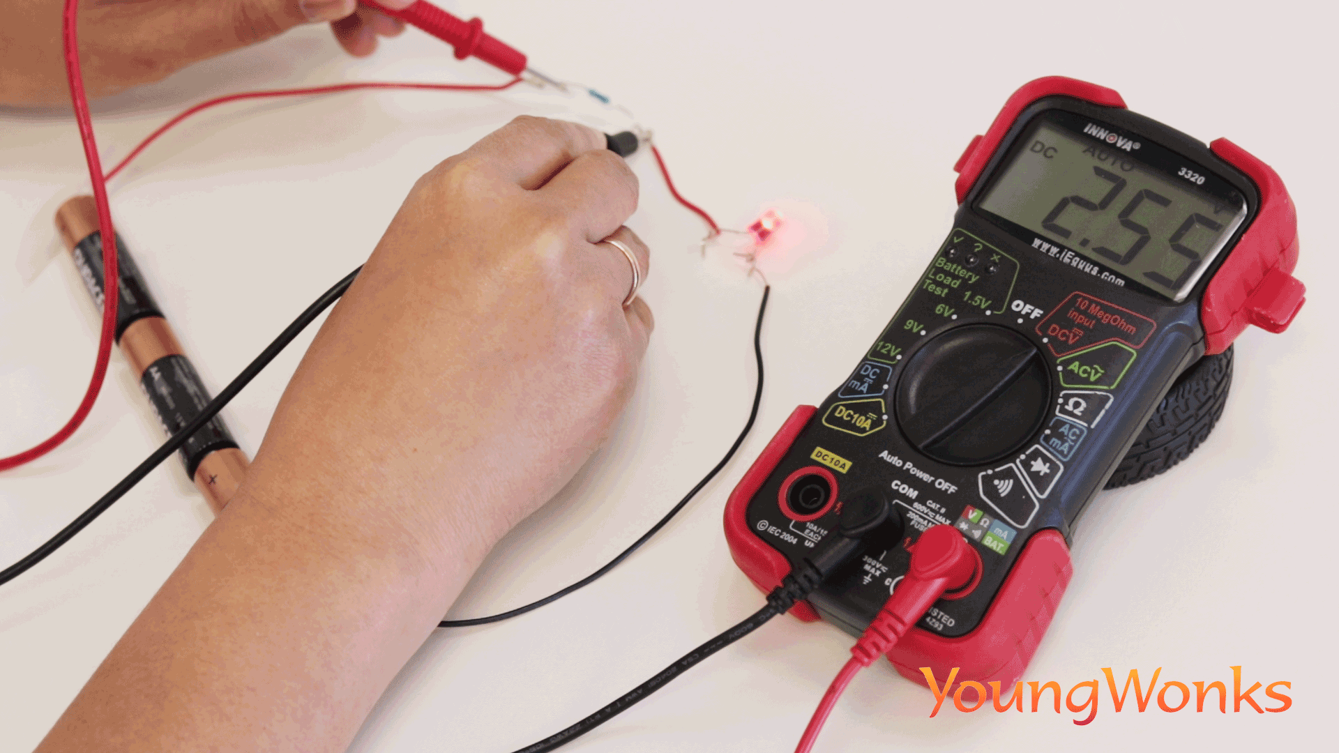
Similarly, if you wish to check the voltage across the resistor, you can do as shown in the image below; it is shown to be 2.55V.
Using a multimeter to measure the current
Again, first let’s take a look at what is current. An electric current is the rate of flow of electric charge. The common symbol used to denote current is I and the unit for electric current is ampere.
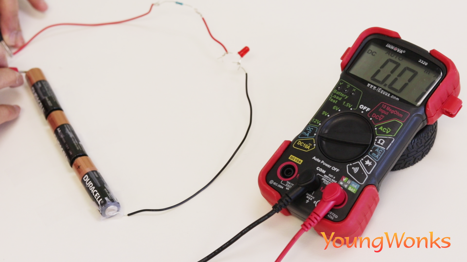
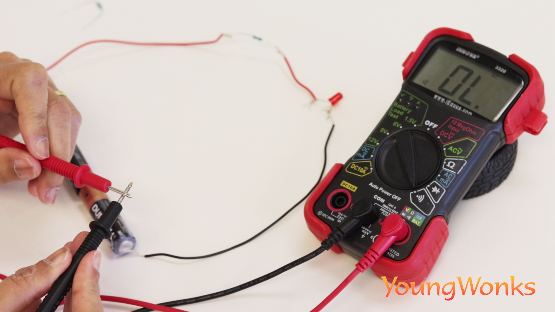
Now reading current is tricky because you have to measure current in a series circuit. So while voltage is measured with the voltage common collector and ground in parallel circuits, to measure current you have to physically interrupt the flow of current and put the meter in-line. So you first turn the multimeter's dial/ knob to the Current mode, followed by pulling out the red wire going to the resistor, and connecting the black probe from the multimeter to it. You then connect the multimeter’s red probe to the positive terminal of the power source, so you can measure the current flowing through the circuit. As you can see in the image below, the current is being calculated as 0.01 milliampere.
Using a multimeter to measure the resistance
So what is resistance? The electrical resistance of an object is a measure of its opposition to the flow of electric current. Resistance is denoted by the symbol R and its SI unit is the ohm (Ω).
The inverse quantity is electrical conductance, and refers to the ease with which an electric current flows. The resistance of an object itself depends largely on the material it is made of—objects made of electrical insulators like rubber have very high resistance and low conductivity, whereas objects made of electrical conductors such as metals have very low resistance and high conductivity. Resistance or conductivity then is used to quantify this material dependence.
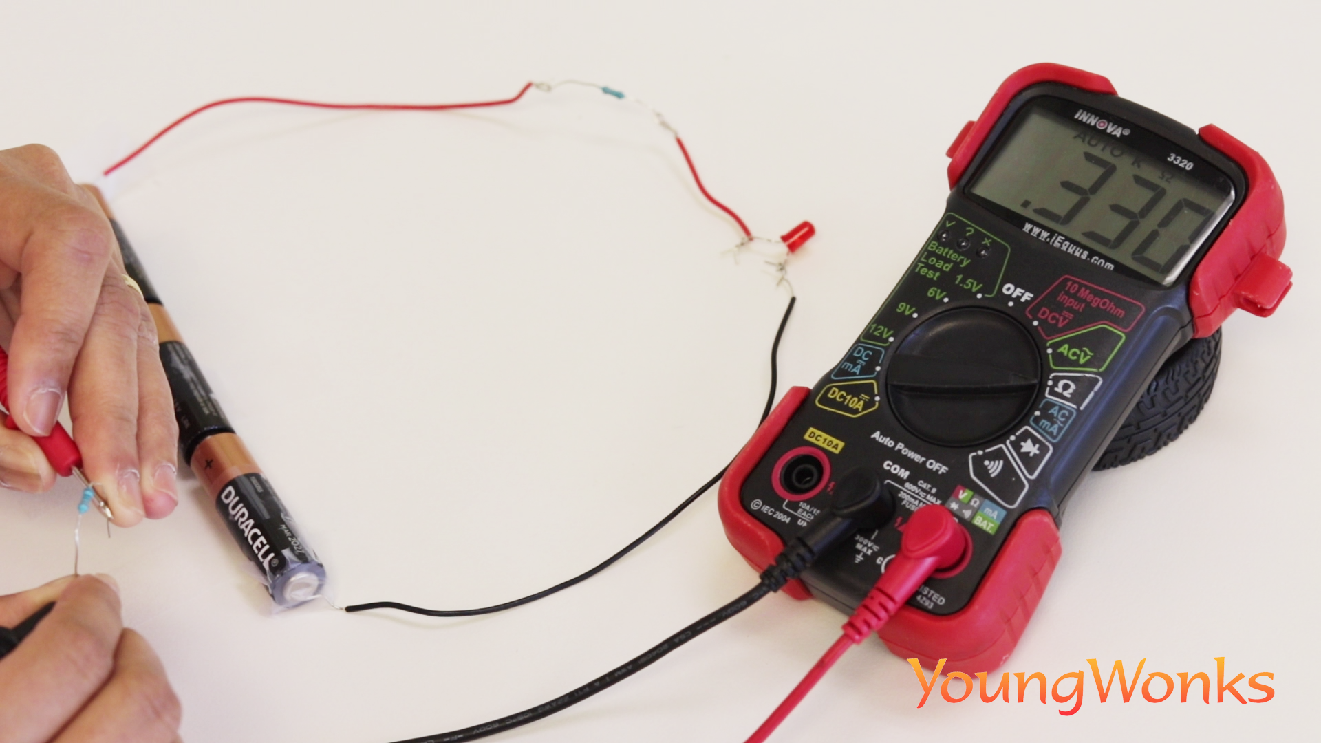
Back to measuring resistance with the multimeter, you begin by turning the knob / dial to the resistance mode. Then you connect the black and red probes of the multimeter to the two ends of the resistor. As you can see in the image below, the resistance is calculated as 0.330 kΩ (kilo Ohms) or 330Ω (Ohms).
Using a multimeter to check the conductivity
Now some multimeters can also be used to check for conductivity. In fact, such multimeters are preferred over the ones that don’t have them. Here the multimeter determines if an electrical path can be established between two points; so one can use it to check if an electrical circuit can be made between them.
In other words, conductivity testing refers to testing the resistance between two points. If there is very low (less than a few Ωs) or no resistance between two points that have been connected electrically, a sound / tone is produced by the multimeter indicating the high conductivity. On the other hand, if there is resistance no tone is produced indicating less/ no conductivity. This test helps to check if connections have been made correctly between two points. This test also helps us recognise if two points are connected that should not be.
So to check for conductivity, turn the knob to the conductivity mode as shown in the image below. Now you can check the conductivity between two points by placing the two probes on the two points. So for example, as shown in the image, if you wish to check conductivity between the probes, you connect the two and you’ll hear the sharp tone/ sound that is produced, which means the two probes are conductive.
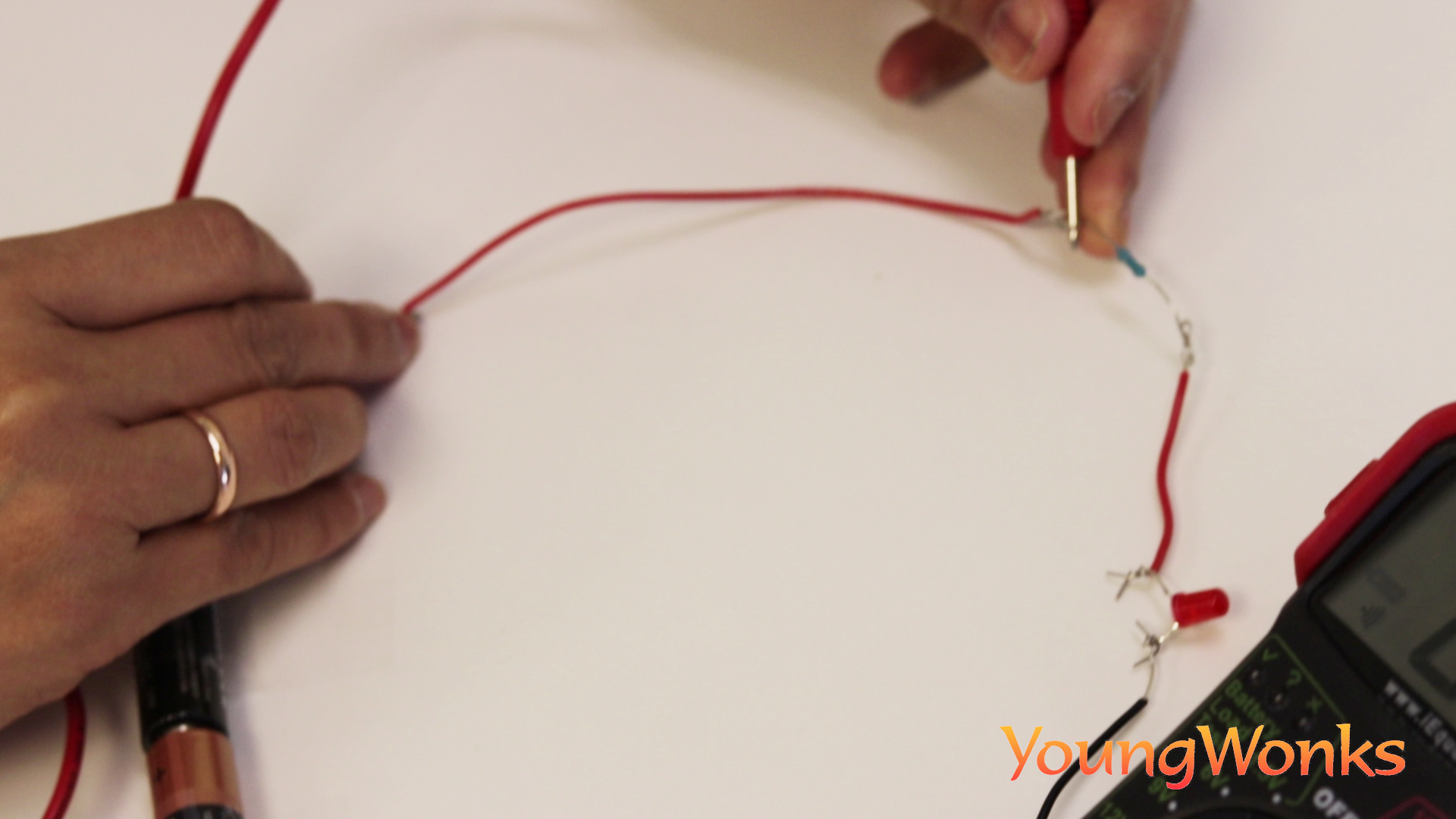
Similarly, you can check the conductivity between any two points; say two points in a regular wire - the beginning and end of the wire as shown below.
You can also check for conductivity between two points of a medal (typically made out of a metal; as shown here).
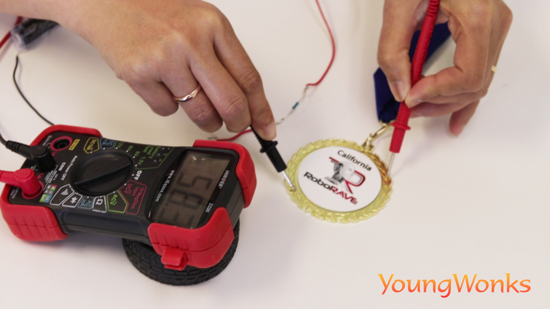
In both the above cases, you’ll hear the tone indicating high conductivity.
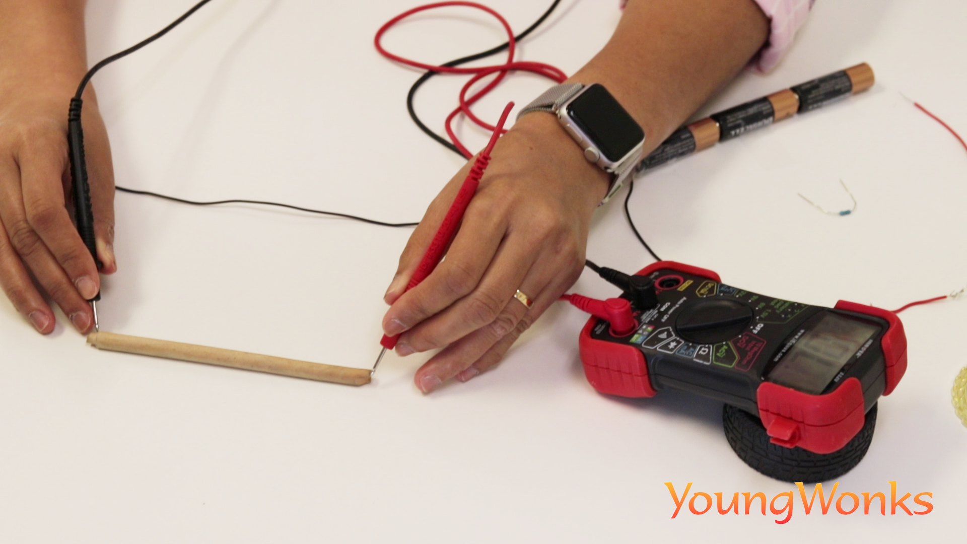
But when you connect the probes to two ends of a wooden piece as shown below, you’ll find no tone being emitted. This means that the wooden piece is not conductive.
Bear in mind that all multimeters take readings over some time and then give you the average, so you can expect the reading to fluctuate. In general, cheaper meters tend to average more harshly and respond more slowly, so keep that in mind when you note the readings.
In the fascinating world of IoT and robotics projects, the role of multimeters cannot be understated. These versatile devices are indispensable for measuring a wide range of electrical parameters, making them an essential tool in the arsenal of young engineers and coders at YoungWonks. Whether you're delving into Raspberry Pi projects or exploring the realms of Arduino, understanding how to use a multimeter effectively is key. To embark on this exciting journey of learning, check out YoungWonks' engaging coding classes for kids on our homepage and discover our specialized courses in Raspberry Pi, Arduino, and Game Development Coding Classes for a hands-on experience in the world of coding and engineering.
Below is a video on the subject:
*Contributors: Written by Vidya Prabhu; Lead image by: Leonel Cruz