May 12, 2022 By Team YoungWonks *
What is a raspberry pi? Raspberry pi is a credit card size computer, created by the Raspberry Pi Foundation, to aid in the learning of computing and problem solving. It allows us to interact with the external world by writing some code. It runs an open-source Linux operating system called Raspbian.
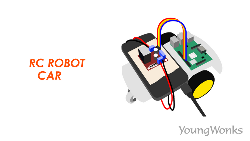
This is a simple step-by-step tutorial to create your very own raspberry pi robot car using basic motors. The robot involves some python programming to control the robot. You will not need a breadboard or any soldering to build this robot.
Refer to the link given below for first time setup of raspberry pi:
https://projects.raspberrypi.org/en/projects/raspberry-pi-setting-up
Using your raspberry pi, refer the link below:
https://projects.raspberrypi.org/en/projects/raspberry-pi-using
Requirements:
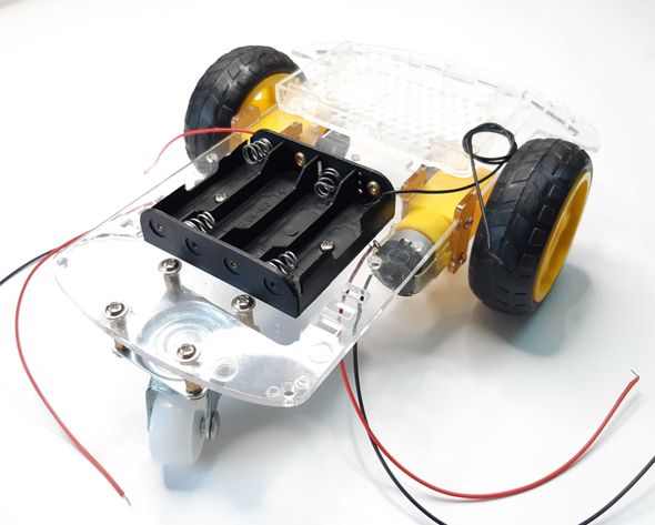
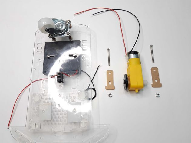
1. Robot Chassis
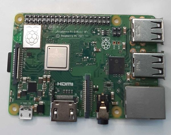
2. Raspberry Pi 3B+ (preferred)
Note: You may also use any other version of the raspberry pi. ex: raspberry pi zero
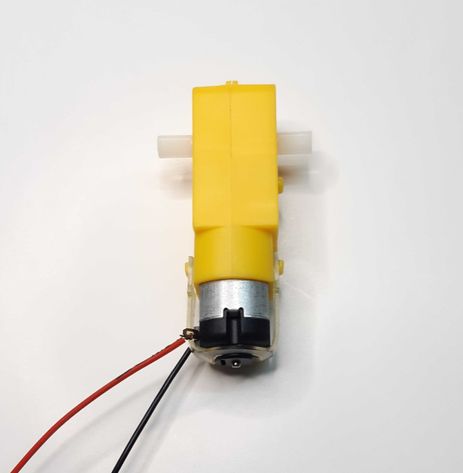
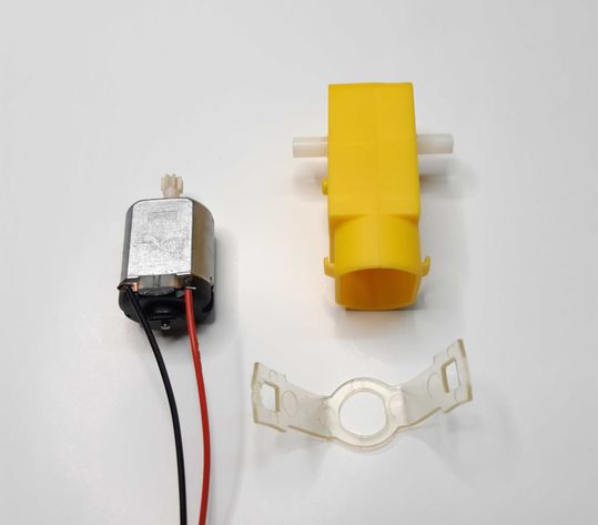
3. DC Motors x 2 (included in robot chassis kit)
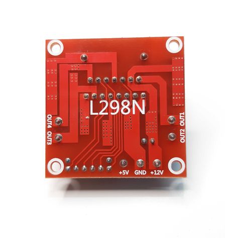
4. L298N Dual H Bridge (DC motor driver)
5. Power Bank of 2.1 A or more output rating
6. Jumper wires (included in Raspberry Pi CanaKit)
7. Switch (included in Robot Car chassis)
8. Tool box
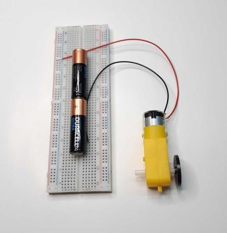
Understanding Working of DC Motors
DC or direct current motors are electrical energy to mechanical energy converters. The current supplied to the motor creates a magnetic field that in turn creates a push pull tension that makes the shaft rotate. The direction of rotation can be changed by changing the flow of current.
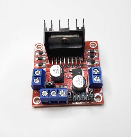
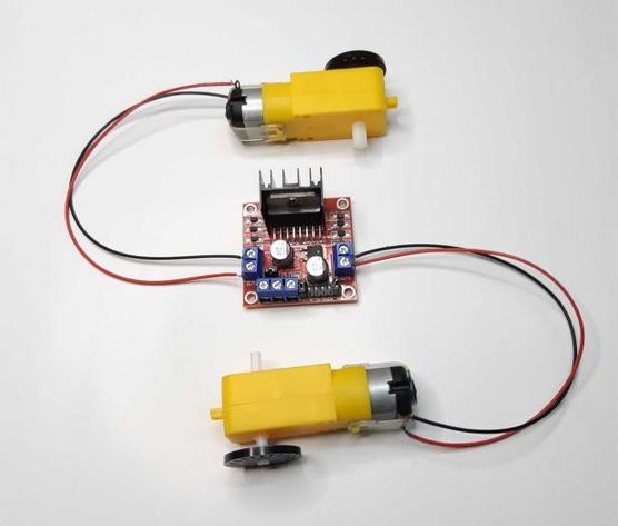
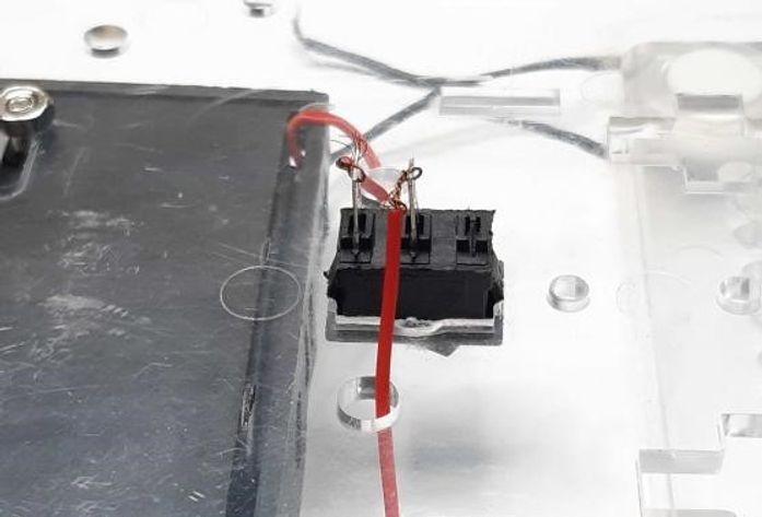
Understanding Working of DC Motor Driver or L298 Dual H-bridge
The H-bridge serves as the motor controller board and can control two such dc motors based on the input current provided. These two DC motors will serve the purpose of either wheel of the robot car. The black structure on the H-bridge is called heat sink that helps the chip to stay cool while operating for longer duration. There are four IN pins for input connections that are internally connected to four other OUT pins, two on left and two on right. In other words, IN1, IN2, IN3 and IN4 are connected to OUT1, OUT2, OUT3 and OUT4 respectively.

Assembling the Robot Car
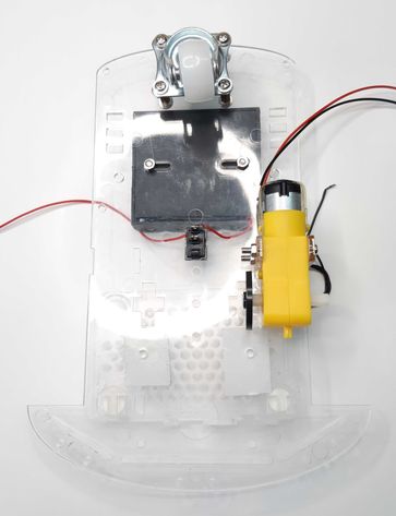
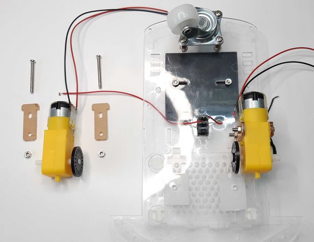
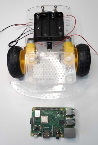
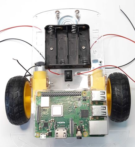
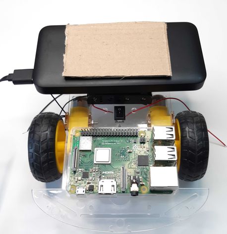
Step 1: The Chassis
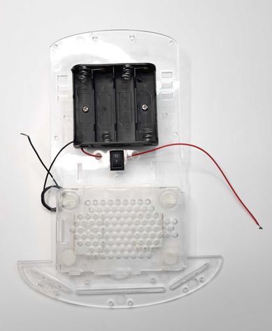
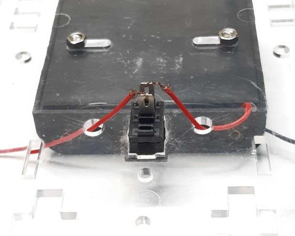
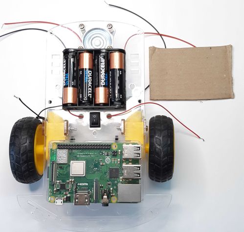
The chassis is the skeleton that will help us to mount all the necessary components on it in order to complete the robot car assembly. Let us start with permanent connections on the robot car. First comes the battery holder that you can attach on the top of the chassis using a pair of screws. Adding a switch is optional that can control the power supply from the battery pack. Next, attach the bottom case of the raspberry pi at the back of the chassis. This case will prevent any damages or direct contact of the raspberry pi with the chassis. You can use double sided tapes to fix the case. Fix the raspberry pi on the case and it sits on it firmly. Do not try to shake the case otherwise the Pi may fall out.
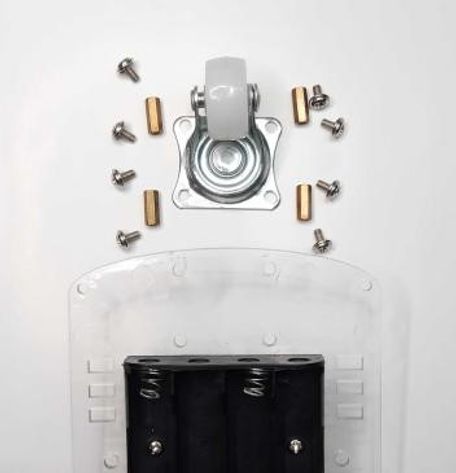
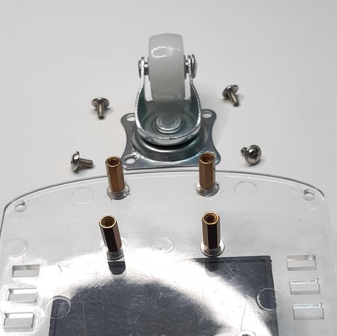
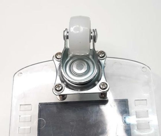
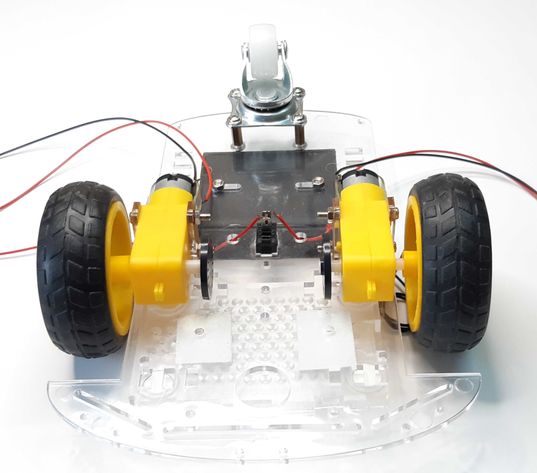
Step 2: Front Wheel
You will receive a 360 degree rotating wheel that will be installed at the front of the chassis. Use the screw set to do the same. Refer to the images below:
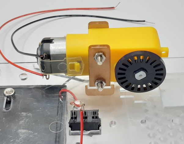
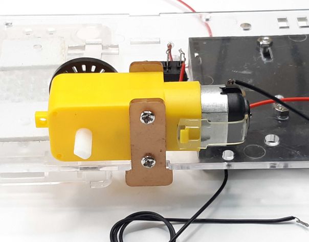
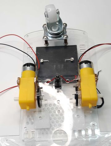
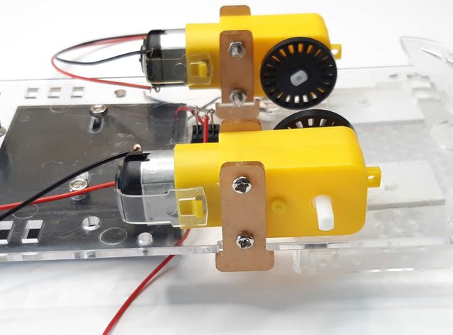
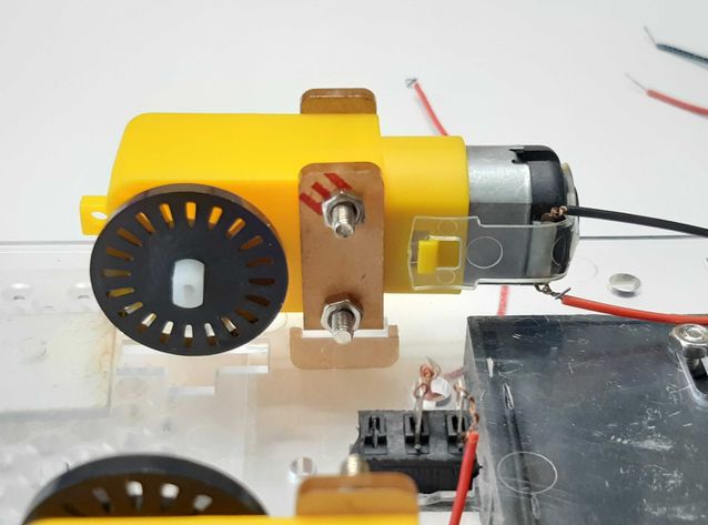
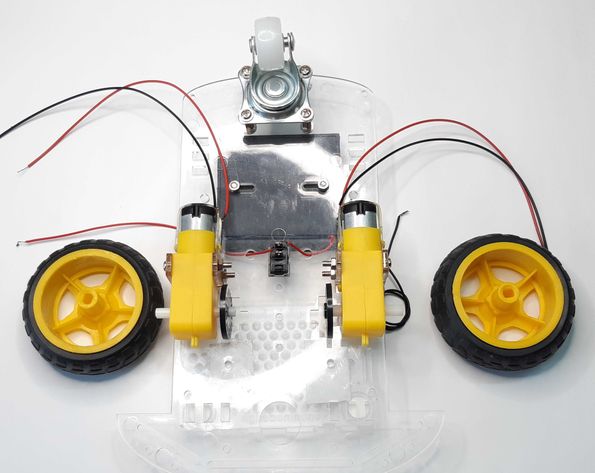
Step 3: Installing DC Motors on both sides
Installation of DC motors on the chassis is bit tricky part. We have to have tiny hands to reach some corners in order to fix screws and nuts. The DC motors will be fixed on both sides of the chassis along with the two wheels. Make sure the wires coming out of the motor should be inwards for better reach of wires to the L298N DC motor driver. We will discuss about the H-bridge in the later part. For now, let’s focus on the motors. Use the long screws and the t-shaped holders to fix the motors on to the sides. This process requires a little patience and steady hands. Refer to the images below for visual guide.
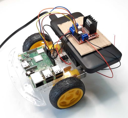
Step 4: Fixing Power bank
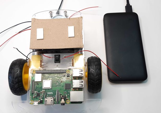
There are two power sources in our robot, the power bank is used to power the raspberry pi 3 whereas the battery pack is used to power the motors through the H-bridge.
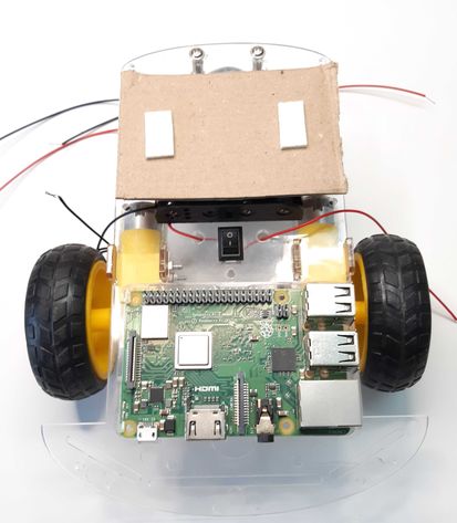
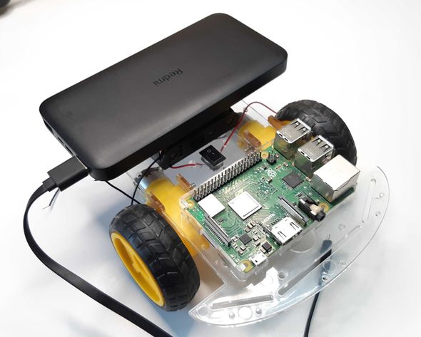
Fix 4 AA batteries to the battery holder. We are going to make the power bank sit on the batteries. Before that, make use of a thick cardboard layer on the batteries to prevent the power bank to come in direct contact. You can make use of a double-sided tape to stick the power bank.
Step 5: Installing L298N H-bridge DC motor driver
Use more double-sided tapes to make the H-bridge sit tight on the power bank. Make sure the H-bridge Is facing you while you stick it on the power bank. This will help us better connect the wheels with it.
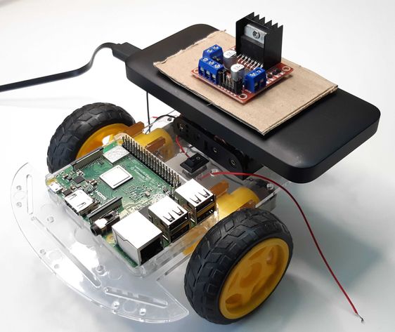
Step 6: H-bridge and wheels connections
As you can see the H-bridge with 4 IN pins facing towards you, connect the wires of the left DC motor to the OUT1 and OUT2 pins of the bridge. Connect the right-handed side DC motor wires to the OUT3 and OUT4 pins of the bridge.
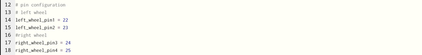
Choose 4 in/out raspberry pi GPIO pins, we have selected 22, 23, 24 and 25 GPIO pins, for the control of wheels through the DC motor driver. Connect these GPIO pins from raspberry pi to the 4 IN pins on the H-bridge circuit board I.e., IN1, IN2, IN3 and IN4. We have chosen these pin numbers to make things simpler. In other words, we know exactly which pins is for which wheel and that cancels out any doubt or confusion.
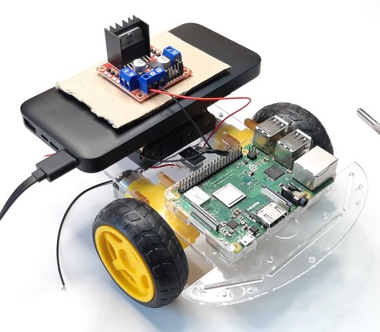
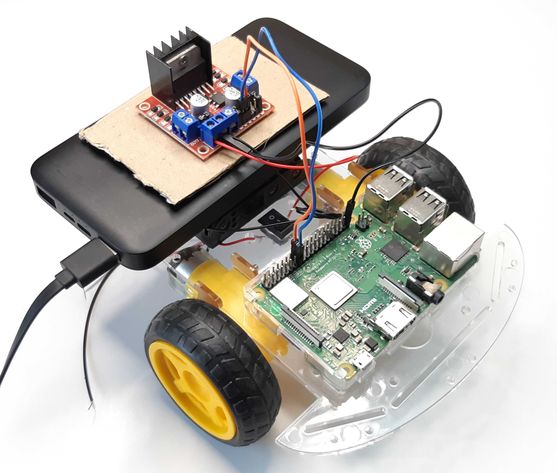
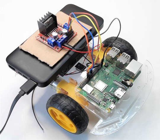
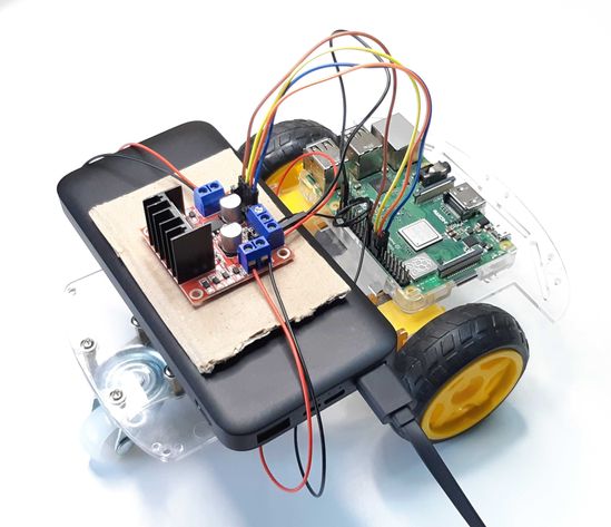
There are three more pins in blue color in the front of the H-bridge. They are 12V, GND, and 5V pins for power input that will power up the H-bridge. Connect the live (red) wire from the battery pack to the 12V pin. Connect the neutral (black) wire from the battery pack to the GND pin of the H-bridge. On the same GND pin of the H-bridge connect a ground from the raspberry pi.
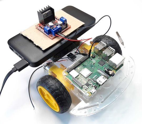
Step 7: Powering up the Raspberry Pi and H-Bridge
We are at the final step of the robot car assembly. Connect the Raspberry Pi with the power bank using a compatible USB cable. The Raspberry Pi should power up and the red LED on it should be ON. The Pi will flash a green light for a moment that indicates that the OS is booting up and ready to go. The green LED with stop flashing after that. Open VNC viewer on you computer, enter the IP address of the Raspberry Pi, verify the credentials and there you go, you have the Pi desktop on your computer screen.
We are now left with the power supply from the battery pack to the DC motor. Do you remember the switch from step 1? Switch it ON. You should be able to see a red LED on DC driver lighting up. If that does not happen, then make sure you go through the steps again and check the wire connections. Try to fix any lose ends.
Coming back to the Raspberry Pi desktop. The Raspberry Pi offers many python IDEs that you can choose from based on which one you are comfortable with. Here we are going to use mu IDE for programming the robot car.
Programming the Robot Car
After the robot car is assembled, it’s now time to program it. Below are the step-by-step python code that we are going to use to make the robot car work.
Step 1: Importing modules
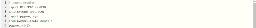
Line 2: Import GPIO method from Raspberry Pi module as GPIO
Line 3: Set the mode operation as BCM (broadcom)
Line 4: Import pygame and sys modules
Line 5: Import all the methods and functions from pygame.locals. This will help us in key press and release events
Line 6: Initialize the pygame essential engine
Step 2: Make the pygame screen

Line 9: Create a variable SCREEN_SIZE to save the width and the height of the pygame screen
Line 10: Create a pygame screen object that will store the screen of mentioned size
Line 11: set_caption() method names the screen with a custom name that user can provide
Step 3: Choosing pins from Raspberry Pi
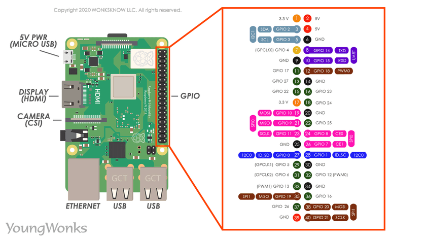
Refer to pin configuration chart of Raspberry Pi, one is given below, to choose 4 pins for the two wheels attached to the DC Motor and store them in different variables.
Step 4: Setting up pins

Setup the pins that we selected on Raspberry Pi using the GPIO.setup() method. This code recognizes the pins are output pins. This mean that the pins will be used for supplying signals and nothing else. We have created a list of all four pins and supplied to the method.
Step 5: Create variables for directions

Create variables for all four directions. We will make use of these variables to change direction of movement of the robot car. Set all the variable to False at the beginning.
Step 6: Minimum required pygame code
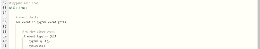
Start with forever while loop and then create a for loop to check all possible events that can occur on the pygame window.
Line 36: Use a for loop to iterate over all occurred events on pygame screen
Line 39: Use condition to check if the pygame screen was closed by clicking on the close button then the screen will be closed.
Line 40. Quit the pygame module
Line 41: Close the pygame screen
Step 7: Check which key was pressed
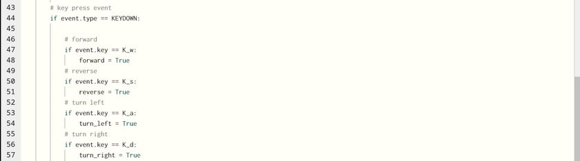
We are still inside the check events for loop
Line 44: If the event occurred was key press or KEYDOWN
Line 47: After the key press, check which key was pressed. This line shows if the key ‘w’ was pressed then make the forward variable True.
Similarly do the same for other direction variables. Here we have used keys w, a, s and d all four directions.
Step 8: Key release events
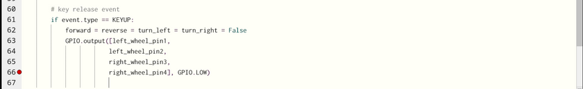
We do not want our robot car to keep moving after we have released the arrow keys. Therefore, we have the KEYUP event that checks if any key was released.
Line 61: The if condition checks if any key was released
Line 62: Set all the direction variables back to False
Line 63: Set all the pins of Raspberry Pi to LOW so that none of the pins can make any wheel rotate and the car stops at its position.
Step 9: What to do if any of the direction variables were set to True
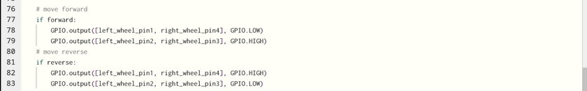
These set of if conditions will start on a new line outside of the event check for loop.
Line 77: If forward variable was set to True, then set one pin on left wheel and one pin on right wheel high. This part of the program required little testing because at this moment we are not sure if the setting a pin is going to make the car move forward or backwards. Therefore, we will leave this portion for later. Similarly, do it for reverse movement. You can observe that the pin settings have become opposite.
Step 10: All directions
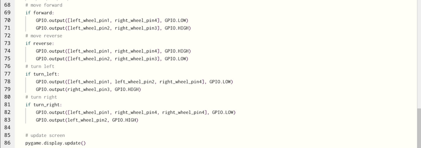
At the final stage of the program, movement of all the directions have been created using if conditions. As mentioned in the last step that this part requires a little testing, because running the program will some time make the wheels move unexpected ways and can cause movement errors. Everything comes to a conclusion that the car will not respond effectively to the key commands.
Line 86: This line simply updates the pygame screen in case we are displaying anything on the pygame screen. Otherwise, the screen will remain blank.
Now it is time to test the robot car. Run the program, test the movement of the car based on the key that you press. If the car does not respond appropriately to the commands, then go back to the program and change the pin settings and test again. This will eventually make your robot car work absolutely fine based on the key press.
Conclusion
After this article, we are aware of Raspberry Pi, it’s installation and Raspberry Pi OS operations. We looked at different electrical devices and learnt about its functions. Then we looked on how DC motor works with and without L298N H-bridge or DC motor driver. Then came the part where we looked at the assembly of the robot car using the chassis or the main frame, Raspberry Pi, batteries, power bank, the H-bridge along with wire connections. Later we programmed the robot car and made it move in all 4 directions.
Further
You can consider extending the abilities of your robot with some sensors such as a distance sensor for obstacle avoidance. You can also look at publishing your code to github. Check out more raspberry pi projects from YoungWonks.
We hope this article helped you to make your own robot car without any prior knowledge of python programming, electrical and hardware assembly.
Enhance Your Coding Skills with YoungWonks
If you're fascinated by the possibility of creating your own remote-controlled robot car and eager to learn more about coding, YoungWonks offers an exceptional opportunity. Our Coding Classes for Kids are tailored to ignite young minds' passion for technology and innovation. Specifically, our Python Coding Classes for Kids provide the foundational knowledge necessary for programming projects just like this. For those interested in taking their skills to the next level, our classes on Raspberry Pi, Arduino and Game Development Coding Classes are designed to offer hands-on experience with real-world applications. Join us to embark on a thrilling learning adventure where creativity meets technology.
*Contributors: Written by Kashif Arbaz; Lead image by Shivendra Singh