Jun 17, 2021 By Team YoungWonks *
What is an oscilloscope? If you are an avid maker, chances are you already know what it is and where it is used. And even if you do not, there is no reason to fret for our latest blog focuses on this very electronic test instrument…
What is an Oscilloscope?

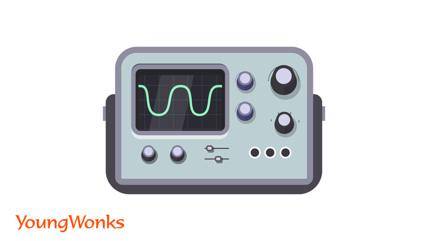
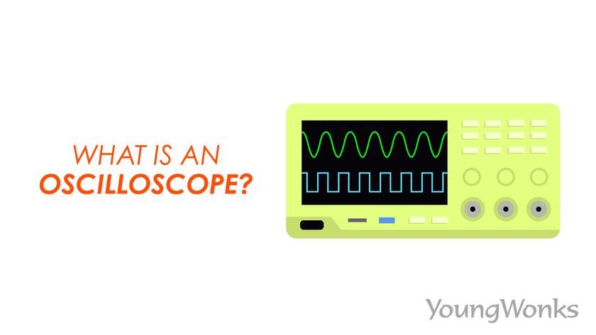
As mentioned above, an oscilloscope is an electronic test instrument. It graphically indicates changes in the signal voltage, typically as a two-dimensional plot of one or more signals as a function of time. So basically, an oscilloscope shows waveforms on some form of display. Sound or vibration signals - too can be deduced from the oscilloscope; however, this is done by converting them into voltage signals.
In other words, oscilloscopes show the change of an electrical signal over time, with time and voltage representing the X and Y axes respectively. The resulting waveform is similar to that of the ripples one sees on the surface of a pond when a stone is dropped into it. This waveform being displayed is used to make inferences about properties such as amplitude, frequency, rise time, time interval, distortion, etc. In fact, oscilloscopes derive their name from the fact that they are used to track/ view oscillations aka changes.
Oscilloscopes have to be adjusted so that repetitive signals show up as a continuous shape on the screen. A storage oscilloscope can capture a single event and display it continuously, so the user can monitor events that typically happen for too brief a time to be seen directly.
It is important to note the difference between an oscilloscope and multimeter, especially the digital variety. A digital multimeter helps with exact measurements of discrete signals, thereby making possible readings of up to eight digits of resolution for the voltage, current, or resistance of a signal. An oscilloscope, on the other hand, depicts waveforms in order to show signal strength, wave shape, and the value of a signal.
Parts of an Oscilloscope

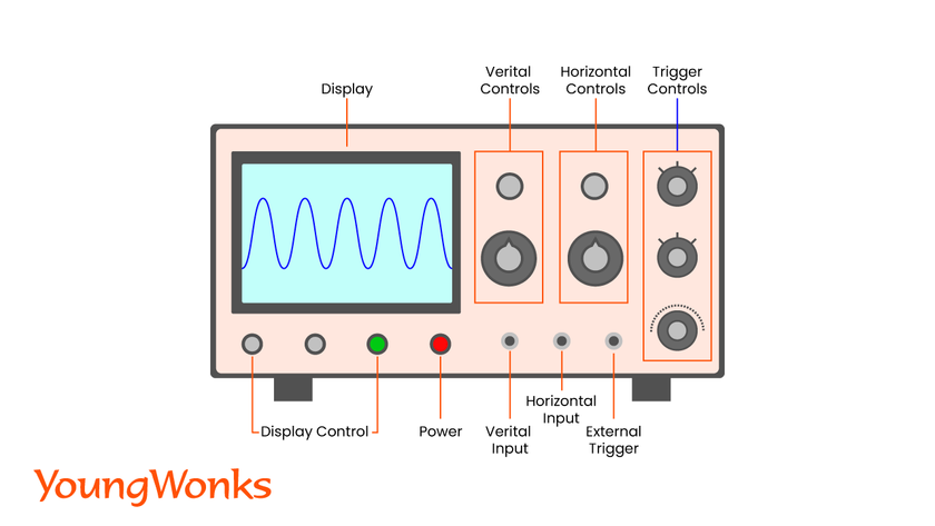
Oscilloscopes basically measure voltage waves. So on an oscilloscope display, voltage is shown on the Y axis (aka vertical axis) and time is represented on the X axis (horizontal axis). The intensity or brightness of the display is sometimes called the Z axis. A simple oscilloscope typically has three systems – the vertical system, horizontal system, and trigger system. Each system has a role to play when it comes to allowing the oscilloscope to accurately reconstruct a signal. Sections labeled vertical, horizontal, and trigger make up the front panel.
The display, earlier a CRT (Cathode Ray Tube) and today an LCD (Liquid Crystal Display) panel, has horizontal and vertical reference lines called the graticule. The vertical section, with a volts-per-division (Volts/Div) selector knob, an AC/DC/Ground selector switch and the vertical (primary) input for the instrument, controls the amplitude of the displayed signal. The section also has a vertical beam position knob.
The horizontal section, meanwhile, has the horizontal beam position knob, a horizontal input for plotting dual X-Y axis signals and the Seconds-per-Division (Sec/Div) selector switch, which is the primary control. This is how the horizontal section controls the time base (sweep) of the oscilloscope.
The trigger section controls the start event of the sweep. The trigger can be made to respond to an internal or external event or to automatically restart after each sweep. The source and coupling selector switches, the external trigger input (EXT Input) and level adjustment form the main controls of this section.
The trigger controls let us stabilize and display a repeating waveform; a common form of triggering is edge triggering. In this mode, the trigger level and slope controls provide the basic trigger point definition. The slope control decides if the trigger point is on the rising or the falling edge of a signal, and where on the edge the trigger point occurs is determined by the level control.
Many oscilloscopes today also come equipped with a probe. An oscilloscope probe is essentially a device making a physical and electrical connection between a test point or signal source and the input of an oscilloscope. Depending on one's measurement needs, the connection can be made with a length of wire or an active differential probe. Such a probe has a resistor of ten times the oscilloscope’s input impedance; some have a switch that lets the operator bypass the resistor when needed. Today, there are two main types of current probes for oscilloscopes: AC (Alternating Current) current probes and AC/DC (Direct Current) current probes.
Earlier, calculation of values using an oscilloscope meant having to manually measure the waveform against the scales built into the screen of the instrument.
Modern digital instruments may calculate and display these properties directly. A basic oscilloscope has a bandwidth of up to 200 MHz and is found in almost every design laboratory, education lab, service center and manufacturing environment.
How does an Oscilloscope Work?

Analog oscilloscopes
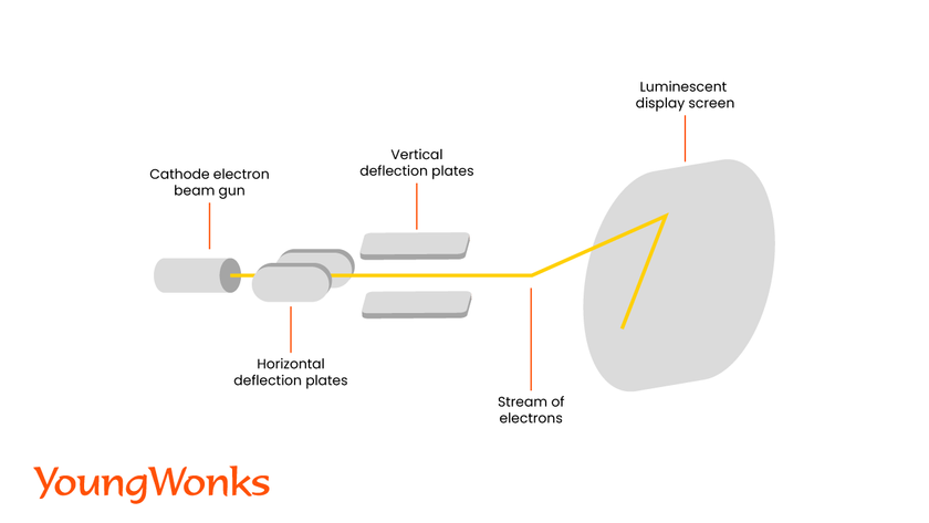
An oscilloscope works in pretty much the same way as a CRT television. For instance, the electron beams in a tv scan back and forth across a screen coated on the back with phosphors. These phosphors light up whenever the beam hits the screen. So when the electron beams fall on the whole screen, they brighten up the phosphors thus forming an image on the screen. This happens time and again and rather quickly - within the blink of an eye, in fact. Thus we end up seeing moving pictures as opposed to a series of still images.
In an oscilloscope, the electron beams work in the same fashion except that they brighten up the phosphors to form a graph. So when a line is displayed on the screen of an oscilloscope, it is being caused by an electron beam going up and down.
In a traditional / analog oscilloscope, the electrical signals going into the x and y connections become the x and y values on the chart displayed on-screen.
Electronic graphs in digital oscilloscopes
How does an oscilloscope draw a trace? This can be explained with the help of an example. So picture a scenario where one has a pencil in one’s hand at the zero point on a graph paper. Now your hand is strapped to two electric motors, both of which are in turn connected to electronic circuits that can test signals of different kinds. Moreover, one of the motors can move your hand in a vertical (y) direction, even as the other moves the hand in the horizontal (x) direction.
Now say, we connect the x-circuit to an electronic quartz clock. So when the clock ticks, it sends a signal to the x motor thus moving your hand to the right, thereby making you draw a horizontal line. Similarly, we go on to connect the y-circuit to an electronic instrument tracking a person’s heartbeat. With the x and y circuits connected at the same time, your hand will move across the page, but it will jump up vertically each time the heart beats. This, in effect, is what happens in an oscilloscope too; except the pencil is the electronic beam and the graph paper is the screen.
Uses / Applications of Oscilloscopes

Oscilloscopes are used in several fields today - be it sciences, medicine, engineering, automotive or the telecommunications industry. General-purpose oscilloscopes are used for maintenance of electronic equipment and laboratory work. For instance, within radio frequency (RF) design, general electronics circuit design, electronics manufacturing, service, repair or an area where electronic circuits and the waveforms on them have to be observed. In fact, troubleshooting with an oscilloscope is a common and rather reliable method for analyzing modern electronic circuitry.
Special-purpose oscilloscopes, as the name suggests, are used with a specific aim in mind, say, displaying the waveform of the heartbeat as an electrocardiogram or analyzing an automotive ignition system. Oscilloscopes can be bought from Tektronix, a leading manufacturer of test and measurement devices including oscilloscopes, logic analyzers, and video and mobile test equipment. Tektronix also provides oscilloscope calibration services.
Shared below are key areas where oscilloscopes are used:
Engineering: Electronic, sound and computer design engineering rely heavily on oscilloscopes -be it carrying out complicated measurements or tracking sound and engine vibrations.
Electronics: Electronic technicians, including those who service and repair household and business electronics such as televisions, computers, and audio video systems, use oscilloscopes for testing equipment, parts and assemblies in these devices.
Healthcare: Oscilloscopes are used as medical measuring instruments; especially to check for heart irregularities.
Sciences (Physics): Oscilloscopes are extensively used for diagnosis in the scientific community, and enjoy greater demand from physicists who tend to regularly use them for several applications.
Vehicle Repair: Mechanics use oscilloscopes to test fuel injectors or to examine and repair a car in a no-start condition.
Types of Oscilloscopes
Cathode Ray Oscilloscope (CRO)
This is the earliest and simplest type of oscilloscope that was made up of a cathode ray tube, a vertical amplifier, a timebase, a horizontal amplifier and a power supply. Now referred to as analog oscilloscopes to distinguish them from the digital ones that shot to popularity in the 1990s, these CROs do not always include a calibrated reference grid for size measurement of waves, and they may not show waves in the conventional sense of a line segment sweeping from left to right. But they could be used for signal analysis by putting a reference signal into one axis and the signal to measure into the other axis. Today’s oscilloscopes boast greater functionality than these CROs.
Dual-beam oscilloscope
The dual-beam analog oscilloscope can send out two signals at the same time. A special dual-beam CRT produces and deflects the two different beams. A dual-trace analog oscilloscope can simulate a dual-beam display with chop and alternate sweeps, but simultaneous displays are still lacking here. This is where a dual-beam oscilloscope fares better: unlike the dual trace oscilloscope, it can switch quickly between traces, and capture two fast transient events.
Analog storage oscilloscope
Trace storage is the extra feature in these oscilloscopes that dwell on the use of direct-view storage CRTs. Storage allows the trace pattern to stay on the screen for several minutes as opposed to a fraction of a second.
Digital oscilloscopes
Here the analog-to-digital converter (ADC) measures the voltages and converts into digital information. The digital storage oscilloscope, or DSO for short, is the standard oscilloscope model used today in several industrial applications, and even by hobbyists due to the low costs of entry-level oscilloscopes. Digital memory comes into play here and sample data is stored for as long as needed without worries about degradation and or the brightness issue one faces with storage-type CRTs.
A DSO also makes possible the complex processing of the signal by high-speed digital signal processing circuits. The two key specs of a digital scope are its analog bandwidth and its sampling rate (or sample rate). While the analog bandwidth helps determine if we can accurately measure a signal with a given frequency, a sample rate is the number of samples an oscilloscope can acquire per second. If the sample rate is not fast enough, one will not be able to see the signal accurately on the oscilloscope screen. So the resolution of the waveform depends on the sample rate.
Mixed-signal oscilloscopes
A mixed-signal oscilloscope (MSO) has two kinds of inputs, a small number of analog channels (2-4), and a greater number of digital channels (usually 16). It can accurately time-correlate analog and digital channels. Digital channels can be grouped and shown as a bus with each bus value shown at the bottom of the display. Triggers can be set across analog and digital channels on many MSOs.
PC-based oscilloscopes
As the name suggests, these are digital oscilloscopes that need a PC platform for display and control. These can be a standalone oscilloscope with a built-in PC platform, or an oscilloscope which connects externally to a PC or laptop through USB or LAN.
Handheld oscilloscopes
Used mainly for test and field service applications, handheld oscilloscopes today are typically digital sampling oscilloscopes. The ground reference voltage is common to all input channels for many of these hand-held oscilloscopes. So when two or more measurement channels are used simultaneously, all the input signals have the same voltage reference, i.e. the earth.
Mixed-domain oscilloscopes
A mixed-domain oscilloscope (MDO) is an oscilloscope that comes with an additional RF input which is used only for FFT-based spectrum analysis. Often, this RF input offers a higher bandwidth than the conventional analog input channels.
The following video demonstrates how to use a modern oscilloscope:

Unlock Your Child's Potential with YoungWonks Coding Classes
For parents and guardians aiming to spark an interest in electronics and programming within their children, finding the right educational resources is crucial. Coding Classes for Kids offered by YoungWonks not only introduce young minds to the fundamentals of coding but also immerse them in hands-on projects that are both engaging and informative. For those particularly interested in enhancing their programming skills, YoungWonks provides Python Coding Classes for Kids, which cover everything from basic syntax to complex problem-solving strategies. Additionally, for kids fascinated by hardware and the physical components of computing, the Raspberry Pi, Arduino, and Game Development Coding Classes can be the perfect gateway into the world of electronics, robotics, and game creation.
*Contributors: Written by Vidya Prabhu; Lead image by: Leonel Cruz
